
GRINDING
Grinding represents a process that is done on the grinding machine where the roll surface is brought into an optimal condition by fine stock removal of roll material measured in micrones (value of roughness and stock removal).
Grinding operations prevent later splashing and popping of chrome layer from the roll surface which can result as a chrome peeling. After rolling operation, rolls have to be re-ground to remove metallurgically damaged stock to limit costs where stock removal has to be sufficient to ensure roll surface quality in next rolling.
SRSC is equipped with state of the art grinder model WS 450 x 5500 mm CNC MonolithTM made by German machine manufacturer HERKULES Maschinenfabrik Siegen, and this model is dedicated for Rolling Mills work rolls by using brand new sophisticated computer systems:
- Integrated fully flexible computer controlled continuous path crowning system (profile measurement system)
- Integrated in-process roll measuring system also for adaptive control for “on the fly” correction grinding (grinding to tolerance, matching of roll diameters, etc.)
- Eddy current crack detection system
- Ultrasonic roll sub-surface inspection system
- Automatic adjusting system of roll steadies for holding the rolls
- Roll history data storage system (capacity 600 rolls)
- Consistent repeatable roughness (Ra)
Technical characteristics of SRSC Herkules grinder:
- Production capacity ……………………. up to 600 rolls/month (if stock removal not exceeding 0,25 mm per roll)
- Roll dim. …………………………………… Dmin.= ∅300 mm Dmax= ∅900–1080 mm, Lmax = 5500 mm (min. and max. diameter of the roll barrel and overall length)
- Roll neck dim. ………………………… Druk.= ∅130–500 mm (min. and max. diameter of the roll neck that can accept steady rest)
- Max. carrying capacity ……………….. Tmax= 12 tonne (max. weight of the work roll that can be treated on CNC grinder)
- Stock removal range…………………… 0,1 – 5 mm (0,1–0,25 mm for CRM rolls, and 0,3–5 mm for HSM rolls)
- Roughness range ………………………. Ra= 0,5 – 2,2 µm


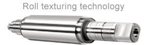
ROLL TEXTURING


HARD CHROME PLATING


NONE DESTRUCTIVE TESTING
SRSC in daily practice of processing rolls apply special NDT testing, so-called “None Destructive Testing” testing and by the methods of penetrant testing and magnetic particle testing, which are applied by the certified engineers who owns appropriate licenses.
Dye penetrant testing – on previously cleaned and degreased surface penetrant is applied (usually red). After penetrating the eventual crack (during penetration is about 10-15 min.), it removes the penetrant in an appropriate manner (water, dry cloth). At penetrants that need to be removed by water have to be careful and to direct water jet parallel to the metal surface, in order to not displacing penetrant from the cracks. After drying the metal surface with a dry cloth, it applies a developer who is usually a white color that brings out the penetrant from the cracks, so that on the white metal surface it is easily visible penetrant red line from the cracks. If there is a crack in the tested metal resepctively roll barrel, then the developer will draw penetrant on its side, which will be disclosed as easy to see the red line of penetrant from the cracks in the white (from the developer) the metal surface.<.p>
Magnetic particle testing – ferromagnetic material to be exposed to the functioning of the magnetic field, and then to the metal surface apply the iron particles (dry or in liquid suspension). Errors on the surface or right below the metal surface (up to 6 mm deep) produce magnetic poles or distort the magnetic field so that these particles are grouped in places such mistakes and give a visible indication of faults on the surface of the material.