


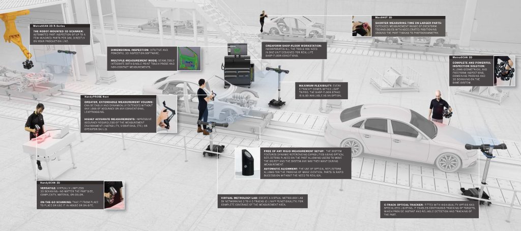
3D Digital CMM Scanning
3D scanning with a CMM (Coordinate Measuring Machine) is a method used to create a detailed digital representation of a physical object by capturing its geometry. This process combines the precision of a CMM with the capabilities of 3D scanning to provide highly accurate 3D measurements and reverse engineering of highly complex machine’s parts or tools.
3D Scanning Applications
3D scanning has emerged as a critical tool in every step of the product lifecycle management (PLM)process. This is especially true of the new generation of truly portable, self-positioning scanners.
The ability of 3D scanning to bridge the gap between physical objects in the real world and the digital design environment has become extremely valuable in a wide range of industries that use PLM – aerospace,automotive, consumer products, manufacturing, and heavy industries among the principal ones.
These industries benefit from faster time to market,improved quality, reduced warehousing costs, and better understanding of product performance.

Reverse Engineering
Reverse engineering is a process that involves measuring a physical object and reconstructing it as a 3D model to recover the design intent—a perfect reconstruction of the original design—in terms of simple analytical surfaces (planes, cylinders, etc.) and freeform surfaces (NURBS) in order to produce a new reference CAD model.
As CAD engineers and industrial designers, you have the critical task of adapting and maintaining parts with shapes that are frequently organic and complex. Since the CAD models are often no longer available or difficult to find, you have to reconstruct the 3D models and integrate them into the design.
The reasons for reverse engineering are multiple: to replace damaged components (for which CAD models are non-existent), to update obsolete parts, to fit new parts into a current assembly or environment, to generate new manufacturing plans, or simply to analyse competitors’ product features. 3D scanners are generally the preferred technology for extracting dimensional information and representing it as a point cloud or an automatic and instant mesh.
SRSC’ high performance Creaform MetraSCAN Black EliteTM enable our CAD engineers to create 3D models from existing physical objects. In addition, scan-to-CAD software VXelement offers to our clients the flexibility to clean, align, and optimize the scanned data, and it allows you to extract dimensional information from the mesh before transferring it to CAD software.
High-resolution, versatile, easy-to-use, and quick 3D scanning tools and software are the solutions to fulfill your goals and overcome your challenges.
- High level of detail: With high resolution for intricate details and full color support, the scan quality is impeccable for modeling freeform surfaces and showing the smallest features.
- Versatility: With advanced laser and optical technologies and limitless scanning volumes, 3D scanners can measure any part, regardless of size, shape, material, surface finish, and complexity.
- Simplicity: With a plug-and-play device and a user-friendly interface, scanning objects without preparation has never been easier, regardless of the user’s experience.
- Speed: Unlike a point cloud, the generated mesh is already lightened and processed, ready to be integrated seamlessly into your preferred reverse engineering, CAD, or 3D printing software.
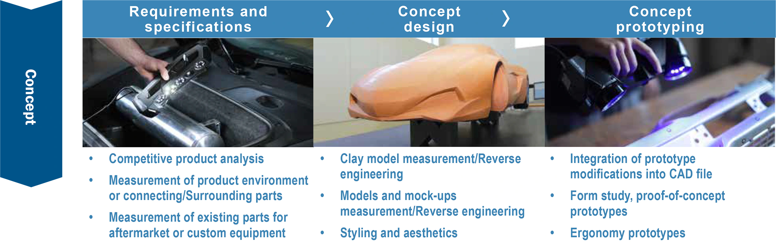
3D scanning in PLM: concept
3D scanning is used in the concept stage of PLM for a wide variety of processes, including determining requirements and specifications, concept design (including reverse engineering) and concept prototyping.
How can you design parts for automotive aftermarket without access to cad files?
Challenge
Countless car brands and models and no CAD file
Designing parts for the automotive aftermarket can be a challenge because of the multitudeof car brands and models in circulation. Further complicating the situation, new models are launched each year. Thus, how can a part, such as an interior carpet, be designed to fit every type of car, model, and year available on the market? How can these parts be designed effectively when the CAD files for the car interior are rarely accessible? How can parts be designed successfully when measurements are taken on complex geometries and, therefore,traditional manual methods of measurement are too restrictive and do not lead to precise data?
Solution
Using portable 3D scanning technology to generate highly detailed CAD files
The solution for designing custom-made parts for each car model is a portable 3D scanner.The 3D scanning tool requires minimum setup, and it can be used to scan the inside of a vehicle quickly and directly at the car dealer. Moreover, it enables the automotive aftermarket part designer to design an accessory for any model, year, and brand of car. Finally, it enables the company to offer a complete catalog to its customers and to be at the forefront of the market with new accessories available as soon as a new car model is released.
Benefit
Faster, easier, and more efficient product development
With a portable 3D scanner, scan-to-CAD becomes a breeze, enabling product developmentto be faster, easier, and more efficient. It is faster because the product development is done correctly the first time. It is easier because the plug-and-play tool generates automatic STL surfaces and outputs mesh files directly. Finally, it is more efficient because the cost of product development is optimized and cheaper than traditional manual methods. Moreover, the design quality is superior because the scanning tool measures all the surfaces with more than half a million points per second for obtaining better product specifications and properties. Finally, the user who opted for a portable 3D scanner as a design tool was the first supplier to make such an offer to his customers, giving him a competitive advantage on the market.
3D scanning in PLM: design
3D scanning is used in the design stage of PLM for computer-aided design (CAD); rapid prototyping; and testing, simulation and analysis (CFD, FEA).

Rapid prototyping when accurately converting clay models into cad files
Challenge
Digitizing complex physical objects for prototypes
When designing a first prototype, it is wise to make a physical model first in order to hold it and try it. Indeed, the physical reality is often different from the CAD models. Thus, a first prototype will enable designers to make modifications to style lines and ensure a perfect design. In addition, it is interesting to look at what the market is already offering to ensure that the foreseen design is better than what the competition offers. However, what rapid prototyping phases need to be monitored or archived digitally? How should one take this information and bring it back to CAD software? How should complex physical objects be digitized?How should the proof of concept be made?
Solution
Clay models and 3D scanning
When designing complex shapes, the easiest approach is often to use claymodels, which can be converted easily into 3D models. Designers and engineers have the flexibility and freedom to play with the prototypes until they achieve the perfect shape. 3D scanning can rapidly digitize complex shapes in high resolution for a fast and accurate conversion of the clay models into CAD files.
Benefit
Accelerate time-to-market for new products
3D scanning technology offers a versatile and user-friendly solution that yields accurate measurements quickly while eliminating the need for long measurement sessions and costly prototypes. The competition analysis is done quickly, the design of the part is done efficiently, and the modifications are integrated into the CAD model easily. Thus, a lot of time is saved, allowing designers to acceleratethe time-to-market for their new products.
3D scanning in PLM: manufacturing
3D scanning is used in the manufacturing stage of PLM for applications such as tooling design, assembly and production, and quality control.

Accelerating the iterative process in tool design with intermediate quality checks
Challenge
Reducing the number of iterations when designinga tooling
When designing a tooling, an iterative process of quality control ensures thatthe part built from the mold, jig, or dye is built correctly and meets the technical requirements. The process involves producing a part, measuring it, analyzing deviations, and performing iterations on the tooling. This method, involving many iterations, can be lengthy, especially if the inspections are performed on a CMM. How can the number of iterations for tooling development be reduced? How can the inspection process be speed up? How can the PPAP and FAI be passed quickly in order to start production without delay?
Solution
Better and faster results with colormap
Opting for 3D scanning instead of touch probing will help accelerate the inspection process. Indeed, 3D scanning technology not only provides production process engineers with better and faster results, but it also offers the colormap,which gives a better visual overview of the part. This way, engineers can quickly adjust the tooling, produce a first part, and, thus, pass the first article inspection.
Benefit
CMM now accessible and numberof iterations optimized
Quality controls made at each iteration with an alternative measuring tool reduce the bottlenecks at the CMM. Thus, the CMM is more available for important inspections with tight tolerances that require its high level of accuracy, such as the final acceptance or critical features. Choosing 3D scanning as an alternative solution to touch probing also optimizes the number of iterations in order to obtain the final tooling more quickly and more efficiently.

Developing, manufacturing, and inspecting a casting of superior quality in less time
Challenge
Inspecting 100% of the surface when producinga casting
When producing a casting, multiple changes are needed to correct elements of the manufacturing process and to produce the part precisely according tothe specifications. How can one ensure that there is enough material before machining? How can the entire surface profiles – not just discrete points – be checked to make sure the part fits within the required tolerances? Howcan reliable data be obtained quickly to avoid unnecessarily extending the development time?
Solution
Better and faster results with colormap
Producing a casting for the aerospace industry requires not only an inspectionof the critical dimensions and wall thicknesses, but also an overall view of the surface plans. In addition, the measurement technology must provide reliableand high-quality data quickly every time a part needs to be inspected. Unlike touch probing, 3D scanning provides an overall view of the inspected part and the surface profiles, and it indicates whether or not there is enough material before machining. In addition, all inspection data is provided quickly and without delay.
Benefit
Accurate casting inspections and impeccablequality control
With 3D scanning, the development time of a casting is shortened and the quality of the part produced is impeccable thanks to the ability of performing root cause analyses. High-quality information is quickly available. The time required forsetup, scanning, and reporting is accelerated. The entire manufacturing process of a casting is improved to produce parts with tight tolerances.
3D scanning is used in the manufacturing stage of PLM for applications such as tooling design, assembly and production, and quality control.
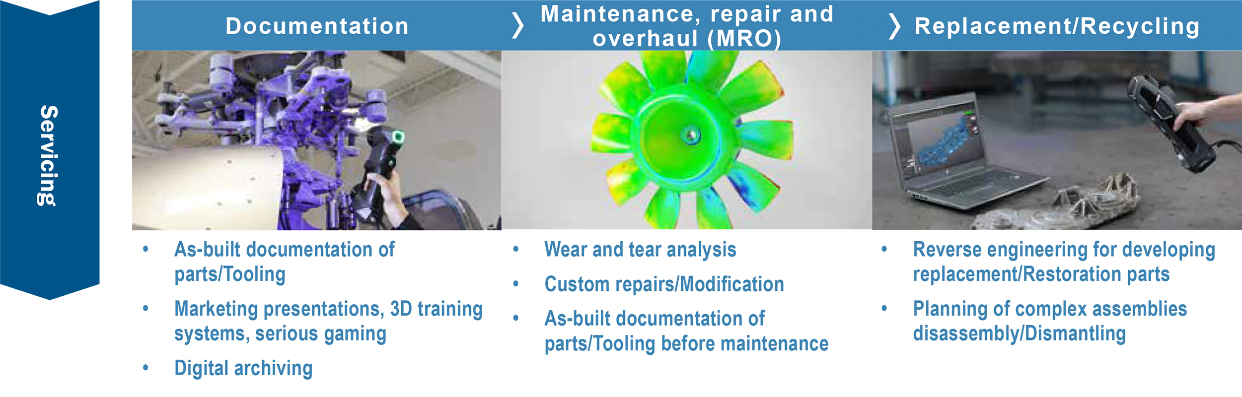
3D scanning in PLM: servicing
3D scanning is used in the servicing stage of PLM for applications such as documentation; maintenance,repair and overhaul (MRO); and replacement, recycling and restoration of parts.
Replacing headers on a main steam piping system at a power generating facility
Challenge
Design without CAD files, using only existing parts
Replacing headers on a main steam piping system at a power generating facilityis challenging. Often, CAD models are no longer available. Therefore, engineers have to design the replacement parts by dealing only with the physical parts.Additionally, headers are often located in very confined, hardly accessible spaces.Then comes the alignment challenge: operators must align the manufactured spherical header with the requisite interface points within tight tolerances on site at the client’s facility. How can these steam piping systems be maintained, how can replacement parts be built, and, finally, how can all of this be done within the allocated time and budget?
Solution
3D capture, 3D model, 2D drawing
The solution is to capture the spherical headers with a 3D scanner and create 3D models based on the captured information. Then, 2D manufacturing drawingsare created and used to manufacture new headers. Once fabricated, the final product is scanned in order to generate a mesh, which is overlaid onto the initial 3D model to check the accuracy with which the headers have been manufactured and to ensure that they have been produced according to design.
Benefit
Perfect fit
With a portable 3D scanner, engineers can go on site and scan the different parts in order to obtain a global assessment of the existing plant. 3D scanning provides engineers with all of the information they need to optimize the design, as wellas all of the dimensions they need to visualize the environment in which their design must fit. From the beginning, they know that the replacement parts will be manufactured precisely and will be consistent with the design. This way, they can be sure that, when reinstalled, the replacement part will be a perfect fit.